|
(-)
Negative single wire pulse data bus door lock circuit

About this circuit:
The
Negative single wire pulse data bus door lock circuit
is a fairly new system used on more and more vehicles. The
vehicles door lock system works on a data bus system (click
here for more on data bus). It sends the lock and unlock
signal to the vehicles Body Control Module or B.C.M. using
only one single wire from the door lock switch. Some
vehicles use a (-) Negative pulse and some use a (+)
positive pulse.
When
installing a remote entry or security system you will only
need to locate one wire.
Most
vehicles will use a (-) Negative pulse to lock and the a
resistant value sent thru the same wire lets say 1500ohms
see resisters
How to determine if your vehicle has this type: the circuit:
-
Follow
directions on What do I
have?
-
Begin by
locating the wire that sends the specific voltage and
while unlocking the vehicles doors and locking them you
will want to look for the change on your test light.
Vehicles that
incorporate the
Negative single wire
pulse data bus door lock circuit
will contain a
total of one wires as follows :
Wire 1
-
Will show a
(+) positive voltage when door lock switch is at rest
-
Will show a
specific (-) negative voltage depending on vehicle, when
locked or unlocked.
You should use a
volt meter on this test as the electronic test light will
not indicate the voltage difference.
For example some
vehicles may show a :
It will vary from
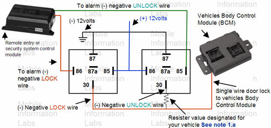
vehicle to vehicle As you see from the picture above the
resister on terminal 30 of the relay will send the
correct resistant to the vehicles data bus line and whala!
doors unlock.
Some vehicles
will have a variable tolerance resister value so in some
case you may get away with lets sat a 1200k ohm
resistor instead of the 1500k required. You should however,
be cautious about sending just any resistant value to the
data bus line, as it may activate something else other than
the door locks.
Determining the resistant value Procedure - Type1
For
NEGATIVE door lock signal wire multiplexing circuits.

-
Locate the lock/unlock
wire for the vehicles door lock system
-
Set the meter to
measure resistant.
-
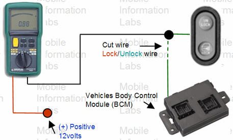
Place the red wire from
the digital millimeter to 12vols positive voltage.
-
Once you have located
the lock un lock wire from the door switch to the Body
Control Module cut it once so that you have two wires.
-
Place the black wire
from the volt ohm meter to the switch side of the door
lock wire as seen in picture above.
-
Press and hold the door
lock switch to the lock position. The meter will now
indicate the proper resistance value to lock the doors.
-
Repeat the same process
for unlock and magic! you've got your resistance value
to unlock doors.
Determining the resistant value Procedure - Type2
If you do
not have a volt ohm meter to measure the resistant values see
Car Stereo and Security Wiring Diagrams
for vehicle specific door lock resistor values, wire
location and wire color. |