|
|
|
 |
How-to-guides - Understanding relays
|
 
|
|
Starting the
Installation of your car security system |
|
Understanding Relays
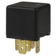
The relay is probably the most
common electronic component that will resolve just about any
electrical issue or complete any project you have.
Understanding the relay will
allow you to isolate a circuit to ruling the free world.
Now let's just see how powerful
the automotive relay can be!
|
Relays
Index
Introduction
Relay aplacations-1
Relay aplacations-2
|
|
|
What's a Relay?
A relay is
an electromechanical switching device when both
power and ground are applied to the ends of a coil,
the relay activates, which causes mechanical contact
points to complete or open a circuit. |
|
One of the
relay’s best features is its ability to use a very
small amount of current to switch large amount of
current.
This ability
helps to make the modern vehicle’s electrical system
as efficient as it is. When
electrical current flows thought wire, the wire has
resistance, which limits the flow.
 The longer
the wires, more electrical current is lost to this
resistance. Devices such as headlights or climate
control allows the circuit to be routed in the shortest, most direct route between the battery, or
source, and the device, or load. The longer
the wires, more electrical current is lost to this
resistance. Devices such as headlights or climate
control allows the circuit to be routed in the shortest, most direct route between the battery, or
source, and the device, or load.
A much
smaller wire is routed to the relay from the
controlling switch. This
arrangement allows for less total wire length, a
smaller gauge wire and more reliable, less expensive
switches.
|
|
How much can it take?
A Standard
Single Pole Double Throw (SPDT) automotive relay’s
coil requires approximately between 130 and 170
milliamps (mA) to activate (between 1 and 2 tenths
of an amp), and the Normally Closed contacts will
switch 30 amps, and the Normally Open contacts 40
amps.
Some
manufactures add a “quenching” resistor across the
coil of the relay to absorb voltage spikes. These
relays with the “quenching” resistor may need up to
170 milliamps (mA) to activate. On the average, most
relays require about 150 mA to activate.
|
|
|
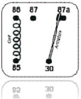
Relay at rest
Coil not engaged |
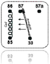
Relay coil activated |
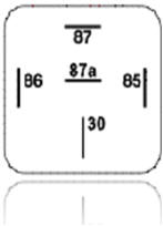
Terminal view of relay |
|
|
How does it work?
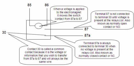
In the above images, note the five terminals, or “pins”. A
relay’s operation is really very simple. Ti
understand its operation, consider the relay as
having two sections, the coil, pins 85 and 86; and
the contacts, pins 30,87 and 87a.
When
negative Ground is supplied to one end of the coil,
and Positive Voltage is supplied at the other end,
the coil creates a magnetic field which activated
the relay.
This magnetic field attracts the
armature, which is attached to pin 30 with a
flexible joint, just like pin 30 to pin 87. The
terms used to describe the contact points thus: pin
30 switches between 87a and 87, so it is “Common” to
both and is usually referred to as COM. In the
relay’s normal condition, at rest, pin 30 is
connected to pin 87a, making pin 87a “Normally
Closed” or NC Pin 87 is not connected to pin 30 at
rest, so its status is “Normally Open” or NO.
|
|
Let's
take it apart.
This type of
relay is defined as “Single Pole Double Throw” or
“SPDT. This term means that the single armature
terminal (or pole, pin30) can be connected (or
thrown) to two other terminals, pins 87a and 87.
The SPDT relay is one of the most useful configurations
due to its flexibility-it can be used as a switching
device, to isolate circuits, to interrupt circuits
and to interrupt and switch at the same time.
 |
|
Now let's see what we can tear up!
On the
following pages there are some relay diagrams which
show how to use relays to perform may functions such
as trigger reversal, starter interrupt, add dime
lights to flashing light output of alarm, using
latching relays to change a pulled output to a
constant output, and many other uses.
These relay
configurations can be very helpful when installing
an alarm, remote start, or keyless entry to perform
different functions in the vehicle o which they are
being installed.
Disclaimer
Mobile Information Labs assumes no responsibility with
regards to the accuracy or currency of this information. Proper
installation in every case is and remains the responsibility of the
installer. MIL, assumes no liability or responsibility resulting
from an improper installation, even in reliance upon this
information.
Continue to next page |
|
|
Copyright © 2001 - 2012 Mobile Information Labs.com
|
|