|
 |
How-to-guides
- Relay applications continued
|
 
|
|
Starting the
Installation of your car security system
|
|
|
|
Saving the day with relays
Here are more
relay circuit designs to solve many obstacles you may
encounter when installing, remote security, remote entry,
and more! |
|
Flashing Lights and Dome Light Supervision from Flashing
Light output with (-) Door Trigger)
The diagram
below shows how to use a couple of Single Pole Double Throw (SPDT) relays to add
Dome light Supervision and Flashing
Light output to the Flashing Light output (White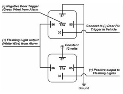 Wire) of an alarm, on a vehicle with (-) Negative Door
Triggers. Example:
This relay configuration can be used to
add Dome light Supervision to an alarm which does not offer
the feature.
When adding
Dome light Supervision to the
Flashing Light output of an alarm, the interior light
flashes the same as the parking lights in the vehicle,
therefore, staying on for 60 or 30 seconds after remote
disarm.
|
|
Flashing Lights and
Dome Light Supervision from Flashing Light output with (+)
Door Trigger
The diagram above shows how to use a
couple of Single Pole Double Throw
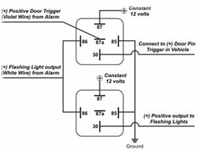 (SPDT)
relays to add Dome light Supervision and Flashing Light
output to the Flashing (SPDT)
relays to add Dome light Supervision and Flashing Light
output to the Flashing
Light output (White Wire) of an
alarm, on a vehicle with (+) Positive Door Triggers.
Example:
This relay configuration can be used to add
Dome light Supervision to an alarm which does not offer the
feature.
When adding Dome light Supervision to the Flashing
Light output of an alarm the interior light flashes the same
as the Parking lights in the vehicle, therefore, staying on
for 60 or 30 seconds after remote disarm.
|
|
Latching Relay (-)
Negative trigger
The diagram above shows how to change a
single (-) Negative Pulse to a constant chassis ground
output using one Single Pole Double Throw (SPDT) relay and a
1 or 2 amp Diode.
Example:
This relay configuration can be
used to change a single (-) pulse to a constant ground for
use with window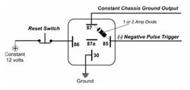 roll-ups, extra lighting, radio accessories or any other
circuit which requires a constant ground instead of one
single (-) Negative pulse.
Warning: Once the relay is
latched it will stay latched until it is reset by opening
the constant 12 volt circuit to pin #86.
The Constant 12
volt input to pin #86 can be “opened” or interrupted using a
momentary contact switch, or relay can be added to the 12
volt input to pin#86 and configured as a normally closed
circuit so that, when the relay energizes, it will interrupt
the 12 volt input and unlatch the “Latching Relay”.
|
|
Latching Relay (+)
Positive Trigger
The diagram above shows how to change a
single (+) Positive Pulse to a constant 12 volt output using
one Single Pole Double Throw (SPDT) relay and a 1 or 2 amp
Diode.
Example:
This relay configuration can be used to
change a single (t) pulse to a constant 12 volt for use
with circuits such as extra lighting, radio accessory
circuits, or any other circuit which requires a constant 12
volt output instead of one single (+) Positive pulse.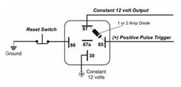
Caution: Once the relay is latched it
will stay latched until it is reset by opening the ground
circuit to pin #86.
The ground input to pin #86 can be
“opened” or interrupted using a momentary contact switch, or
a relay can be added to the ground input to pin #86 and
configured as a normally closed circuit so that, when the
relay energizes, it will interrupt the ground input and
unlatch the “Latching Relay”.
|
|
Disclaimer
Mobile Information Labs assumes no responsibility with
regards to the accuracy or currency of this information. Proper
installation in every case is and remains the responsibility of the
installer. MIL, assumes no liability or responsibility resulting
from an improper installation, even in reliance upon this
information. |
Back to
Understanding relays
|